
Low Voltage(MSB Panel)
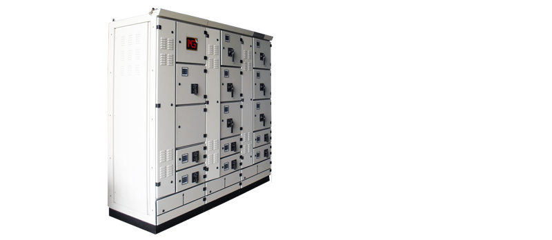
MSB Panel
Features
- Incoming supplies, outgoing and couplings with circuit breakers
- The variable circuit breaker up to 6300A
- Tinned coated and bare copper bus bar are available with heat shirnkable sleeve
- Overcurrent, short circuit, over and under voltage protection
- Incoming supply system for drill-free cable connection
- Individual, fixed installation units on a mounting plate
- Internal separation up to form 4
- Cable entry from the top or bottom
- Cable connection access from front or rear
- Wall mounting or floor mounting and self-standing
- Indoor and Outdoor type
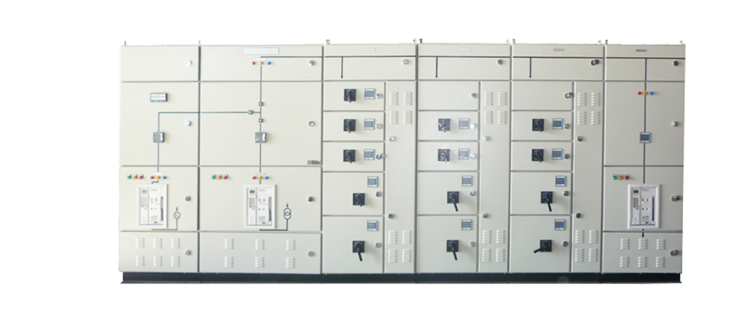
- The AGE switchgear has great application flexibility for Main Distribution Board, Sub Distribution Board, Motor control Centre. .Several assembly configurations are possible, for incoming ,outgoing and bus-ties.
- The dimensions of the compartment per each breaker have been standardized in order to guarantee to the customers the most compact solutions but also a reasonable space for the cable compartment.
- Also the dimensions of the compartment where the main busbar are located have been standardized.
Switchgear panel frame
-The AGE frame is based on modular 2 mm thick still C sections, pre-drilled at a pitch of 25 mm. Each unit is based on modular elements and consists of:
-All compartments are mechanically segregated from the others.
-The switchgear panel is pre set for easy extensions on both sides.
- The compartment is suitable to accept both air and moulded case circuit-breakers and it is accessible from the front side by means of a locked hinged door. The circuit-breakers can be installed in all the available versions, fixed, plug-in and withdrawable. With all the widrawable circuit-breakers, in order do guarantee the maximum safety level to the operator, the apparatus handling can be carried out with the door closed.
- The busbar compartment is located in the middle section of the switchgear. Main busbars can be located at the top, in the centre or at the bottom of the panel depending on the selected design and they distribute the power to the various switchgear panels. In some of the existing configurations main busbars can be directly connected to a circuit-breaker as well. Distribution busbars are located into the single column and positioned vertically to feed panel circuit-breakers. The busbar system can be composed by 1, 2 or 3 busbars per phase, according to requested rated current, short-circuit level and operational ambient conditions in terms of temperature, altitude and humidity. Busbars are normally bare copper made, on request can be suitably treated with tinning, silver-plating and/or sheathing.
- The compartment is suitable to accept both air and moulded case circuit-breakers and it is accessible from the front side by means of a locked hinged door. The circuit-breakers can be installed in all the available versions, fixed, plug-in and withdrawable. With all the widrawable circuit-breakers, in order do guarantee the maximum safety level to the operator, the apparatus handling can be carried out with the door closed.
Cable compartment
-The cable compartment is located in the rear side of the panel and it is accessible by means of a locked hinged door or a removable bolted covers. Its purpose is to contain:
- power terminals
- outgoing cables
- current reducers
- auxiliary terminal blocks (if any).
Cable compartment
-The switchgear is provided with a continuous electrolytic copper earthing busbar, with a cross-section suitable for the proper switchgear shortcircuit rating and pre-set on both sides for connection to the earthing network. Are connected to the earthing busbar:
- all the metallic structures of the individual units
- all not live metallic parts of the circuit-breakers;
- all CTs and VTs secondary earthing connections.
Easy Installation
-Installation and testing duration are considerably reduced as the panel is tested and adjusted in the factory and then delivered as a complete unit.
| Design standard | – | ||
|---|---|---|---|
| Electrical Data | – | ||
| Rated Voltages | Rated insulation voltage | Ui 1000 V AC | |
| Rated operating voltage | Ue 440 V AC | ||
| Degree of pollution | 3 | ||
| Rated frequency | 50 – 60 Hz | ||
| Rated Currents | Main busbars: | Main busbars: | Ie Up to 6300 A |
| Mechanical Characteristics | Frame | Metal Clad and Metal Encloure | |
| Dimensions | Height | 1700,2000,2100,2300 mm | |
| Width | 700, 800, 900,1000,1100,1200 mm | ||
| Dept | 450,600, 800,1000,1100,1200 mm | ||
| Surface Protection | Frame | EGI | |
| Internal subdivision | UNI EN 10130 Zinc coated, Steel | ||
| Transverse section | UNI ISO 4520 Zinc coated, Steel | ||
| Enclosure Power coated | RAL7032 (pebble grey) | ||
| Degrees of Protection (IEC 60529, EN 60529) | With door open | IP 20 | |
| With door close | IP 30 standard up to IP 54 | ||
| Normal Conditions | Installation Internal for service | – | |
| Ambient temperature | min -5°C, max 40°C, average 24h 35°C | ||
| Relative humidity | max 50% at 40°C | ||
| Maximum altitude | ≤ 2000 m | ||
| Extras | Paint finish | External protection | Special colour on request |
| Busbar system | Main and branch busbars | Sheated busbars, treated busbars (Ag/Sn) | |
| Form of separation | According IEC 61439-2 | Up to 4b | |
| Cable |Entry | Top or bottom | ||